51 Ergebnisse gefunden
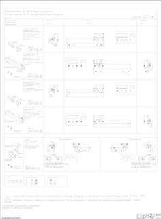
Blockbilder - block diagrams OL 90 N Klapp-auswärts
(PDF | 294 KB)
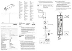
NT 2,5 A-24 V SM DIR
… Wiring diagram Notes on electrical connection: XX The cabling must be carried out in such a way that there is sufficient clearance (> 20 mm) between input and output line and the power line and output line are laid separately XX Always use wire-end ferrules for wire cores XX Insulate wires that are not used XX Wiring diagram of the 24V window drives has to be considered. At 24 V DC and with long supply cable, the cable must have a sufficiently large cross-section to prevent voltage drop. Calculate cross-section! Connection terminals 24 V DC, 2,5 A ∓ ± EN Wiring diagram NT 2,5 A-24 V SM DIR EN Power supply NT 2,5 A-24 V SM DIR 230V AC 195297-01 NT 2,5 A-24 V SM DIR power supply Technical data ID 195293 Mains voltage 220 - 240 V AC +/-10% Mains frequency 50-60 Hz Input current 0,58 A Idling input power 0,24 W Output power 60 W Output voltage 24 V DC ±5% (SELV) Output current 2,5 A, ED 30%,
(PDF | 1 MB)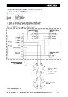
Montageanleitung,Beiblatt EMD F und EMD F-IS mit integriertem Rauchschalter ORS141
… wiring diagram Slimdrive EMD, EMD F Abbreviations GF SF RSZ 24V RSZ GND RS • • • Active leaf drive Fixed leaf drive Input, hold-open + Input, hold-open – Smoke switch Remove Jumper JP1 (black) if circuit breaker is connected Remove Jumper JP2 (red) if additional smoke switches are connected For additional information, see wiring diagram, chapter Smoke switch control unit Door drive EMD F-IS with integrated smoke switch *) GF control unit DCU2-F DCU201 Integrated RS ORS141 ALARM NO 12 JP2 JP1 SF control unit DCU2-F DCU201 RSZ GND 61 61 RSZ GND Second drive 63 63 Second drive RSZ 24V 62 62 RSZ 24V RSZ GND 61 61 RSZ GND ALARM COM 11 ALARM NC 10 Input RS
(PDF | 53 KB)
E 740 Kettenantrieb
… Wiring diagram E740 DE Kettenantrieb GB Chain drive Elektrischer Anschluss E740 / 24 V Elektrischer Anschluss E740 / 230 V Allgemeiner Anschluss Kabelverlegung Bei 24 V DC und langer Zuleitung muss das Kabel einen genügend großen Querschnitt aufweisen, um einen Spannungsabfall vorzubeugen. XX Querschnitt berechnen (siehe Kabelplan für RWA-Zentralen). Die Ansteuerung von mehr als einer Bedienstelle ist mit Selbsthaltemodul (Mat. Nr. 29343) und Tasten möglich. ������������������������������������� ������������������ ����������������� ����������� ������ �������������������� ����� ��������������������� ������������ ������ Anschluss an Notstromsteuerzentralen E260N Für die Leitungsüberwachung nur beim letzten Motor Ader "3" anschließen. ������������� �������������������� Anschluss Max. 10 Antriebe parallel schalten. �������� ��������� ����������� ����� ����������� ����� ������� ������������ Aderfarben: BN = braun BU = blau BK = schwarz GN/YE = grün/gelb ������������ ������������� �������� Der Antrieb darf nicht geöffnet werden! Bei Beschädigung des Anschlusskabels darf ein Ersatz nur durch GEZE erfolgen. ������� ������ �������� ������� ������ �������� ���� ���� �� � ��� Electrical connections E740 / 24 V Electrical connections E740 / 230 V General alignment Cable laying When using a 24 V DC source from a greater distance, the cross-section of connecting cable has to be dimensioned sufficiently large in order to prevent a reduction in voltage. XX Calculate the cross section (see wiring diagram for emergency power control system). Control of more than
(PDF | 173 KB)
End Position Sensor EPS Slimdrive SL NT / Slimdrive SL NT-FR
… Wiring diagram b1 b2 c1 c2 a1 a2 a d
(PDF | 352 KB)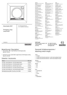
Notschalter LED 1-fach Rahmen AS 500
… Wiring diagram X1 … 48 39 48 20 43 SCT Anschlusspläne / Wiring diagrams Taster / Switches Bezeichnung / Description SCT (1-pol.) SCT (2-pol.) Mat. Nr. / Taster / Switches Mat.No. 117996 118478 Bezeichnung / Mat. Nr. / Description Mat. No. – – TPS TPS-SCT TPS-KDT TPS-KDT-SCT 113231 113232 126582 126583 DPS mit/with OFF DPS ohne/ without OFF DPS mit/with OFF SCT 151524 Schaltplan / Circuit diagram 42 41 44
(PDF | 2 MB)
E 212 R1 /230 V AC, E 212 R /230 V AC, E 212 /24 V DC
… Wiring diagram E 212 R1 / E 212 R / E 212 Inhaltsverzeichnis … 10 Appendix: Wiring diagram E 212 R1 /230 V … I Wiring diagram E 212 R /230 V … II Wiring diagram E 212 /24 V … Safety instructions XX XX XX XX E 212 R1 / E 212 R / E 212 Before the system is approved for operation carry out and log an isolation measurement of the supply network of the system. Use only cables prescribed in the wiring diagram. Implement the cable type, line length and cross-section in accordance with the technical specifications. Always use wire-end ferrules for wire cores. Insulate the cores that are not used. In the case of 24 V DC and a longer power supply cable, the cable must have a sufficiently large cross-section in order to prevent a voltage drop. See cable plan for RWA central control units for cross-section calculation. … Maintenance GEZE prescribes regular maintenance (at least once a year). This is to be carried out by a suitably qualified person. In the process the operation as well as the condition of the mechanical equipment (imbalance or signs of wear, damage to fastening parts) and the electrical connections are to be checked. The system may not be used during repair and setting work. XX Before starting maintenance work, interrupt the power supply (mains and battery) and verify the safe isolation from supply. XX Inspect the fixations and clamping screws for firm seating. XX Clean soiling from the drive during maintenance. Caution: The window closes automatically!! Danger of pinching and clamping! Before installation, read the enclosed safety notes and follow these during installation and operation of the drive! Warranty claims require proper mounting, installation and maintenance in accordance with the manufacturer's specifications. XX XX Inform the electrician by handing out this wiring diagram. The drive must be protected from construction dirt and splash water. GB
(PDF | 2 MB)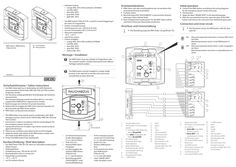
FT4 A
… Wiring diagram àà The RWA button FT4A/24 V DC is used for manual triggering in the event of a hazard (fire). àà Surface-mounted housing àà Switching power max. 100 mA at 24 V DC àà Current consumption LED … The RWA button must be installed in a clearly visible position in the stairwell or corridor and must not be concealed by an open door leaf. àà Der RWA-Taster darf nur in Verbindung mit GEZE-Notstromsteuerzentralen E 260 N (VdS), MBZ 300, THZ und THZ Comfort eingesetzt werden. àà Der Anschluss erfolgt gemäß dem Anschlussplan der Notstromsteuerzentrale. àà Die Leitungsverlegung und der Anschluss darf nur von einer zugelassenen Elektrofirma vorgenommen werden. XX Bestimmungen der örtlichen Feuerwehr beachten. XX Klebeschild mit Angabe der RWA-Taster-Nummer bauseits auf die Innenseite des RWA-Tasters kleben. XX RWA-Taster vor Bauschmutz schützen. àà The RWA button may only be used in combination with GEZE emergency power control units E 260 N (VdS), MBZ 300, THZ and THZ Comfort. àà Connection is made in accordance with the wiring diagram for the emergency power control unit. àà Laying and connection of cables may only be carried out by an approved electrician. XX Observe any conditions prescribed by the local fire brigade. XX Apply the sticker with details of the RWA button number onto the inside of the RWA button on site. XX Protect the RWA button from building dirt. Überwachungswiderstände aktiv, im letzten RWA-Taster der Reihe Monitoring resistors not active, in all predecessors in series Der RWA-Taster muss gut sichtbar im Treppenhaus oder Flur montiert werden und darf nicht durch einen offenen Türflügel verdeckt werden. Sicherheitshinweise / Safety instructions The illustration shows the RWA button with the door opened. ON Montage / Installation 162458-01 Connect the RWA button according to the wiring diagrams for the emergency power control unit used. Test function. Apply the label "SMOKE VENT" in the desired language. After the successful function test, open the door of the RWA button and remove the card cover from behind the glass pane.
(PDF | 1 MB)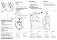
Anschlussplan FT … A Nebenbedienstelle
… Wiring diagram àà àà àà àà àà àà àà Erstinbetriebnahme Aufputzgehäuse Schaltleistung max. 100 mA bei 24 V DC Stromaufnahme LED 2,5 mA bei 24 V Glasscheibe auswechselbar –10 °C ...+55 °C nur für trockene Räume Lieferbare Farbe: àà orange (RAL 2011) XX XX XX XX àà The RWA button FT4 A/24 V DC is used for manual triggering in the event of a hazard (fire). àà The RWA button is a secondary unit with only one display for alarm. àà Can only be used in combination with a main FT4 A button. àà Surface-mounted housing àà Switching power max. 100 mA at 24 V DC àà Current consumption LED … mA at 24 V àà Glass pane replaceable àà –10 °C ...+55 °C àà only for dry rooms àà Colour available: àà orange (RAL 2011) XX Initial operation RWA-Taster nach den Anschlussplänen der verwendeten Notstromsteuerzentrale anschließen. Funktion testen. Beschriftungsschild "RAUCHABZUG" in gewünschter Sprache anbringen (siehe nächste Seite). Nach erfolgreichem Funktionstest Tür des RWA-Tasters öffnen und Karton hinter der Glasscheibe entnehmen. Falls die Taste ZU/Reset nicht angeschlossen ist, Beschriftung „Reset“ (2) abkleben. Anschluss und Innenschaltung XX XX XX XX XX XX Connect the RWA button according to the wiring diagrams for the emergency power control unit used. Test function. Apply the label "SMOKE VENT" in the desired language. After the successful function test, open the door of the RWA button and remove the card cover from behind the glass pane. If the CLOSE/RESET switch is not connected, paste over the "Reset" label (2). Connection and inner circuit XX Die Darstellung zeigt den RWA-Taster mit geöffneter Tür. DIP-Schalter S3 (3) / DIP switch S3 (3): ON Überwachungswiderstände aktiv, im letzten RWA-Taster der Reihe … 126 Sicherheitshinweise / Safety instructions àà Der RWA-Taster darf nur in Verbindung mit GEZE-Notstromsteuerzentralen E 260 N (VdS), MBZ 300, THZ und THZ Comfort eingesetzt werden. àà Der Anschluss erfolgt gemäß dem Anschlussplan der Notstromsteuerzentrale. àà Die Leitungsverlegung und der Anschluss darf nur von einer zugelassenen Elektrofirma vorgenommen werden. XX Bestimmungen der örtlichen Feuerwehr und lokale Anforderungen an RWA-Taster beachten. XX Klebeschild mit Angabe der RWA-Taster-Nummer bauseits auf die Innenseite des RWA-Tasters kleben. XX RWA-Taster vor Bauschmutz schützen. àà The RWA button may only be used in combination with GEZE emergency power control units E 260 N (VdS), MBZ 300, THZ and THZ Comfort. àà Connection is made in accordance with the wiring diagram for the emergency power control unit. àà Laying and connection of cables may only be carried out by an approved electrician. XX Observe any conditions prescribed by the local fire brigade and observe local requirements for RWA buttons. XX Apply the sticker with details of the RWA button number onto the inside of the RWA button on site. XX Protect the RWA button from building dirt. Kurzbeschreibung / Brief description àà Der RWA-Taster FT4 A/24 V DC dient zur manuellen Auslösung bei Gefahr (Feuer). àà Der RWA Taster ist eine Nebenbedienstelle mit nur einer Anzeige für Alarm . àà Nur in Kombination mit einer Hauptbedienstelle FT4 A einsetzbar.
(PDF | 594 KB)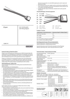
IQ gear
… Wiring diagram YE ZU / CLOSE GN AUF / OPEN BN COM WH Signal RD +24 V BK GND YE GN BN gelb / yellow grün / green braun / brown WH RD BK weiß / white rot / red schwarz / black Funktion / Function Schaltfunktion / Switching function Spannung "Signal" / Voltage "Signal" Ruhe/Stop / Rest/Stop 6V AUF / OPEN 12 V ZU / CLOSE 18 V max. 10 Antriebe pro IQ gear anschließbar / max. 10 drives connectable per IQ gear 152801-01 Antriebsparametrierung / Drive parameterization Standard: Betriebsart "Tasterbetrieb mit Selbsthaltung" Optional: Betriebsart "Schalterbetrieb/Totmann" Standard: Operating mode "Push button operation with self-locking" Optional: Operating mode "Switch operation/dead man's handle" Kurzbeschreibung / Brief description Technische Daten / Technical data (ID 151959) IQ gear ist eine Schnittstelle zur Ansteuerung von GEZE-Fensterantrieben (IQ windowdrives) im Lüftungsbetrieb in Kombination mit Netzteilen und Tastern. Das IQ gear wandelt die Schaltsignale des Tasters in eine Analogspannung um. Diese Analogspannung wird von den Antriebssteuerungen ausgewertet. Versorgungsspannung / Supply voltage Stromaufnahme max. / Max. current consumption Ausgangsspannung / Output voltage Umgebungstemperatur / Ambient temperature Maße / Dimensions Anschlüsse / Connections Ausführung / Version IQ gear is an interface for actuating GEZE window drives (IQ windowdrives) in ventilation operation, in combination with power supply units and push buttons. The IQ gear converts the switching signals of the push button into an analog voltage. This analog voltage is evaluated by the drive controls. Sicherheitshinweise / Safety notes Für die Sicherheit von Personen ist es wichtig, diesen Sicherheitshinweisen Folge zu leisten. Diese Anweisungen sind aufzubewahren! àà Vor Montage beiliegende Sicherheitshinweise lesen und bei Montage und Betrieb des Antriebs beachten. àà Gewährleistungsanschprüche setzten eine fachgerechte Montage, Installation und Wartung nach den Angaben des Herstellers voraus. àà Nur Sachkundige, die von GEZE autorisiert sind, dürfen Montage, Installation und Wartung durchführen. Eigenmächtige Veränderungen an der Anlage schließen jede Haftung von GEZE für daraus resultierende Schäden aus. àà Bei Kombination mit Fremdgeräten übernimmt GEZE keine Gewährleistung. Auch für Reparatur- und Wartungsaufgaben nur GEZE-Originalteile verwenden. àà Der Anschluss an Netzspannung muss von einer Elektrofachkraft durchgeführt werden. Netzanschluss und Schutzleiterprüfung entsprechend VDE 0100 Teil 610 durchführen. àà Den neuesten Stand von Richtlinien, Normen und länderspezifischen Vorschriften beachten. For the safety of persons, it is important to follow these notes on safety. These instructions are to be adhered to! àà Before installation, read the enclosed safety notes and consider them during installation and operation of the drive. àà Warranty claims presuppose a professional assembly, installation and maintenance according to the specifications of the manufacturer. àà Only skilled personnel who are authorized by GEZE may implement assembly, installation and maintenance. Arbitrary changes to the system exclude every liability of GEZE for damages resulting from this. àà In case of combination with devices of other manufacturers, GEZE does not Montageort / Installation location 24 V DC, (20-30 V) 12 mA 6-18 V, ±5% -10... +60°C 29 mm x 25 mm x … per group Taster: mehrere pro Gruppe / Pushbutton: several per group Lüftertaster / Vent switch Netzteile / Power supplies Antriebe / Drives LTA-24-AZ (ID 129393) LTA-LSA (ID 118476) NT 1,1 A-24 V UP (ID 151426) NT 1,5 A-24 V HS (ID 151425) NT 2,5 A-24 V HS (ID 151424) NT 4,2 A-24 V HS (ID 151423) IQ windowdrives: Slimchain, Powerchain, E 250 NT. E 9x0 (siehe Anschlussplan / see wiring diagram ID 148327) Anschluss Antriebe / Connection drives STOP 24V A 24V B Signal LIN +24V GND 12V - +24V GND 18V - +24V GND 6V - Mehrere Netzteile,
(PDF | 586 KB)