31 Ergebnisse gefunden

Revo.PRIME Manuell
Manuelles Karusselltürsystem mit niedriger Kranzhöhe und schmalem Profilsystem für drei- oder vierflügelige Türen
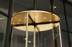
Revo.PRIME Manuell
Dieses Türsystem bekommt die Hauptrolle, wenn es um Gestaltungsfreiraum und Transparenz im Eingangsbereich Ihres Gebäudes geht. Möglich machen dies eine minimale Kranzhöhe von nur 75 mm und ein kaum sichtbarer Antrieb.

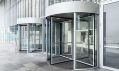
Manuelle Karusselltüren
Manuelle Karusselltüren sorgen für eine leise, elegante und leichte Zugänglichkeit zu Ihrem Gebäude. Sie sind eine bedarfsgerechte Lösung, wenn das Besucheraufkommen und Durchgangsbreiten eher gering sind.
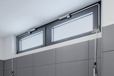
Manuelle Oberlichtöffner
Mit nur einem Griff sorgen manuelle Oberlichtöffner für Frischluft. Auch bei geschlossenem Hauptfenster ist natürliche Lüftung damit einfach und effektiv. Oberlichtfenster machen Räume heller.

TSA 355 Manuell
Hohe Begehfrequenz, ein repräsentativer Gebäudeeingang, ein drei- oder vierflügeliges Türsystem – hier kann das manuelle Karusselltürsystem TSA 355 Manuell seine Stärken voll ausspielen.

TSA 355 Manuell
Manuelles Karusselltürsystem für drei- oder vierflügelige Türen
TSA 325 NT Manuell
Manuelles Karusselltürsystem für drei- oder vierflügelige Türen
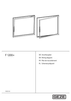
F 1200+
… user, Schulen u.Ä.) XX Gefahrenstellen sensorisch absichern. àà Anwendbar bei Räumen für den regelmäßigen Aufenthalt von schutzbedürftigen Personen, Kinder oder Personen mit eingeschränktem Urteilsvermögen, die nicht in die sichere Nutzung eingewiesen sind oder unbeaufsichtigt sind (z.B. Kindergärten u.Ä.) Normen und Richtlinien XX Den neuesten Stand von Richtlinien, Normen und länderspezifischen Vorschriften beachten, insbesondere: àà DGUV Vorschrift … 21 Blocking manual opening to turn position … 21 Blocking and releasing for authorised users … Reference documents Document Installation instructions F 1200+ (ID 193236) User manual F 1200+ (ID 193469) Window documentation Explanation Mechanical installation of the window drive and the fitting Use, operation, cleaning, maintenance, faults, decommissioning, disassembly, disposal Manufacturer's documentation, see system documentation 17 Intended use … Mechanical risks Risk of injury and death There is a danger of impact, pinching and clamping due to the forces which occur at windows operated by electric motor. Reaching into the movement range of the window unit during operation can lead to injuries. There is an injury risk through manual opening of the leaf to turn position. XX If necessary, apply measures for authorised use of the turn position (see chapter … “Blocking manual opening to turn position”). Special measures to protect hazardous spots Where installation of the leaf or the hazardous spots are below … Functional principle of the drive The F 1200+ drive is a window drive for the automation of large side-hung and bottom-hung windows. The window is moved to tilt or turn position by the F 1200 fitting. The spindle moves linearly. The sword (2) fixed to the drive engages in the driver (1) of the fitting (3). The driver transfers the spindle movement to the driving rod and thus to all moving components of the fitting. The drive has the following drive positions: àà Turn position: The window is unlocked, leaf can be moved manually to the turn position e.g. for manual full ventilation, window cleaning or maintenance àà Locked: The window is closed, all locking points are locked. àà Tilt position: The window opens automatically in the direction of tilt. The drive stroke is 78 mm. The spindle moves as follows: (2) -18 mm; releases the turn position (0) … Product description Overview of the modes of operation You will find information about the modes of operation in the user manual F 1200+ (ID 193469). … Operating displays (LED status display) and control keys Information about the various display and control functions of the LED status display can be found in the user manual F 1200+ (ID 193469). The type of function of the control keys can be configured using the parameter setting unit ST 220 (see chapter 10 “Parameter setting”). The key turn position can be blocked. This prevents the drive moving to this position. … Proximity sensor You will find information about how the proximity sensor works in the user manual F 1200+ (ID 193469). The sensitivity of the proximity sensor can be configured using the parameter setting unit ST 220 (see chapter 10 “Parameter setting”). … Blocking manual opening to turn position Depending on the installation situation of the window (e.g. risk of falling from higher storeys), it can be necessary to completely block opening of the leaf to turn position or restricting this possibility to authorised users (e.g. for cleaning, maintenance). àà Blocking manual opening to turn position, see chapter 10 “Parameter setting” àà Blocking and releasing with lock for authorised users, see chapter … .1 “Blocking and releasing for authorised users” … .1 Blocking and releasing for authorised users A side cap with integrated lock (1) is used as the upper side cap (option, ID 191158 (RAL7012) or ID 191159 (according to RAL)). The turn position is mechanically blocked by the lock. After the lock has been opened using a key (2) and the side cap (1) has been pulled off, manual opening to turn position is released. Information about this release for authorised users can be found in the user manual F 1200+ (ID 193469). … Emergency-opening / emergency-locking of the window If the drive is without power e.g. due to a power failure, the window can be opened or closed manually. You will find information about “emergency-opening” and “emergency-closing” in the user manual F 1200+ (ID 193469). 21 Installation … Test and handover XX XX Check the measures taken to secure against or prevent crushing, impact, shearing and trapping points and implement these. Clean the window unit, remove dirt. Carrying out tests XX Following installation, check the following points: àà Window unit is adjusted properly and works safely. XX Have the window unit checked by an expert. XX Check all the functions by carrying out a trial run. Preparing risk analysis XX Before commissioning the window unit, have a risk analysis carried out by the distributing company (expert qualified electrician) in accordance with the Machinery Directive MLAR 2006/42/EC. àà The “GEZE safety analysis for power-operated windows” can be used as a guide for preparation of the risk analysis. XX Apply CE marking to the unit in accordance with Annex III of the Machinery Directive. Handover procedure XX After completion, Instruct the operator in operation and use of the window unit. XX Hand over unit documentation (wiring diagram and all mutually applicable documents) to the operator or electrician if appropriate. XX Have the operator instruct users (people who operate the window unit, cleaning staff etc.) on safe use and cleaning of the window unit and point out the risks involved with the window unit. … Commissioning Carrying out commissioning Following connection to the 24V supply voltage, the drive system is ready for operation immediately and can be controlled via the control keys. No separate commissioning or teaching run is required. The parameter settings of the drive system can be changed using the parameter setting unit ST 220 (ID 087261) (see chapter 10 “Parameter setting”). 24 F 1200+ window drive 10 Parameter setting Parameter setting The following is possible with the parameter setting unit ST 220: àà Configuration of drive activation àà Blocking the “turn position” control key. This prevents the drive system moving to this position. àà Changing parameter values àà Reading out diagnosis values àà Reading out faults, errors, warnings and displaying information The options for adjusting and setting parameters for the F 1200+ drive system are described in the user manual IQ windowdrives (ID 153523) of the ST 220. … 9 10 11 12 13 14 Connection WINDOW (for single drive / window) Ammeter (for display of the current consumption of the drive/window) Mains connection cable Drive connection cable – Service case Service terminal ST 220 Connection cable ST 220 mini DIN F 1200+ drive 25 Cleaning 11 F 1200+ window drive Cleaning You will find information about cleaning in the user manual F 1200+ (ID 193469-00). 12 Maintenance You will find information about maintenance in the user manual F 1200+ (ID 193469-00). 13 Faults … s or drive and remove obstacle. Drive starts reversal due to a blockage dur- XX Check whether an obstacle blocks window, fitting ing movement or drive and remove obstacle. XX Test smooth running of the door fitting and lubricate if necessary. XX Measure ambient temperature (max. 70 °C) and Switch-off of motor power stage due to thermal overload or overcurrent reduce if possible. XX Check duty rating (max. 30 %) and reduce to maximum value. XX Check whether an obstacle blocks window, fitting Overcurrent cut-off or drive and remove obstacle. XX Regrease all moving parts of the window fitting. XX Check whether all window fitting twistlocks have been set to the minimum contact pressure possible. Decommissioning You will find information about decommissioning in the user manual F 1200+ (ID 193469). 15 Disassembly You will find information about disassembly in the user manual F 1200+ (ID 193469). 16 Disposal You will find information about disposal in the user manual F 1200+ (ID 193469). 26 F 1200+ window drive 17 Technical data Technical data Mechanical data Application window type Force [N] àà Unlock turn position àà Lock and tilt position Opening width [mm] àà Main closing edge Spindle stroke [mm] àà Turn function àà Tilt function Stroke speed [mm/s] on the main closing edge *parameter setting from MIN=11 to MAX=32 Locking time [s] Weight [kg] Dimensions L x B x D [mm] Volume [dBA] Values Turn-and-tilt window, aluminium Electrical data Voltage [V DC] Current consumption [A] Power consumption [W] Duty rating [%] End position cut-off open End position cut-off closed Overload cut-off Function proximity sensor [mm] Integrated control keys Integrated displays Protection rating Values 24 ±10%, SELV
(PDF | 3 MB)
EG-Baumusterprüfbescheinigung GC 334
… user manual in its current valid version must be taken into consideration when using the sensor GC 334. 2. Für eine vollständige Beurteilung einer Sicherheitsfunktion müssen alle Anforderungen gemäß EN ISO 13849-1 und EN 61508 auf die vollständige Sicherheitsfunktion, in der der Sensor GC 334 eingesetzt wird, angewendet werden. For a complete functional safety assessment of a safety function, all requirements of EN ISO 13849-1 and EN 61508 have to be applied to the complete safety function in which sensor GC 334 is used. 3. Die Gültigkeit der Beurteilung ist nur für die im Bericht Nr. 35362648/35362649 spezifizierte Version gegeben. The validity of the assessment is only given for the version as specified in technical report no. 35362648/35362649. Essen, 2024-04-05 TÜV NORD CERT GmbH Essen Zertifizierungsstelle Maschinen Certification Body Machinery Benannte Stelle 0044 / Notified Body 0044 TÜV NORD CERT GmbH Am TÜV
(PDF | 68 KB)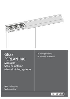
PERLAN 140 Manuelle Schiebesysteme
… Manual sliding systems Wandbefestigung Wall mounting … 21 Symbols and markings This instruction manual uses warning notices which help You to avoid damage to persons or material. u Always read and observe these warning notices! u Follow all the instructions that are given in a warning notice. Warning sign Warning word Description Danger for persons. WARNING Non-observance may lead to death or serious injuries. To point out the correct usage, important information and technical notices are emphasised. Sign Description symbolizes „Important Notice“ symbolizes „Additional Information“ u Sign for an action: This tells You what has to be done. When there are multiple steps, observe their sequence. Product liability Your attention is drawn to the “product liability law“ defined liability to the manufacturer for his products which are contained in the main catalogue (product information, usage, misuses, product activity, product maintenance, the duty to inform and the duty to instruct). Non-compliance with these conditions relieves the manufacturer from any liability. 12 PERLAN 140 … Personnel qualification The mounting and installation instructions list persons as well as the minimum qualification required by them to carry out the work described: ú Users Persons who have no personnel qualification but nevertheless come into contact with the product. ú Personnel Persons whose qualification entitles them to carry out the work described. The designation of the work carried out is often given, for example „Maintenance personnel“. ú Technicians Personnel of a company that carries out mounting or installation of the product. ú Operators Also called end users. The operator may not be the owner of the product (for example the property management). … of the German “Produkthaftungsgesetz” (Product Liability Act - ProdHG) for his products the following information on sliding door gear has to be observed. Non-observance releases the manufacturer from his statutory liability. Product information and proper use Sliding door gears in this definition are gears for sliding leaves and similar sliding elements, called “objects” below, that are usually not moved faster than at walking speed. Sliding door gears are used at perpendicularly mounted leaves made of wood, plastic, glass, aluminium or steel and their corresponding material combinations. A guide is provided at the lower horizontal sides of the leaves. The products designed for shading equipment are corrosion resistant special versions. Proper use includes in particular proper mounting. The gear has to be sufficiently stable at all positions. Functioning of the gear may not be impaired or modified by mounting. A buffer has to be used in the leaf middle to limit the movement. The Perlan 140 AUT may not under any circumstances be used in passage areas or other areas that have a high occurrence of persons. Outdoors the drive unit of the Perlan AUT has to be mounted so that it is not exposed directly to weather influence. Misuse Misuse – meaning any use that is not the proper use – of sliding door gears exists in particular when ú the gears are used with a higher load than the maximum bearing capacity that is specified in the catalogue and in the remaining product documentation, ú improper mounting or insufficient fastening has taken place, ú particularly aggressive media can act on them, ú inappropriately rough bump and fall loads act on them, ú the position of the channel rail deviates too strongly from the horizontal, ú foreign material penetrates the track, ú the rollers are used with excessive speed, ú modifications were carried out that were not agreed with the manufacturer, ú obstructions are inserted into the opening area or between the leaves or the object respectively, thus preventing its proper use, ú additional loads act on leaves or the object, ú if there is an intervention between the leaf and the masking frame when being pushed closed or when closing or if a person or a body part is located within this area when the leaf is pushed closed. Sliding shutters are not a substitute for devices specially designed as burglary prevention devices. 13 Safety PERLAN 140 Any use that does not conform to the “Proper use” and does not conform to the technical specification is an improper use. Warranty claims cannot be asserted for any damage that is not proper use or constitutes improper use. Product performance In as far as the product performance is not specified in concrete forms in our catalogues, brochures, technical specifications and other product instructions, the requirements placed on our fittings have to be agreed with us. Our regulations dealing with the assembly of the fittings are binding. Product care and maintenance Safety-oriented fittings have to be checked regularly for firm seating and wear. Depending on the requirements, the fixing screws are to be tightened or replaced respectively. In addition, the following service and maintenance work has to be carried out at least once a year: ú Check the functionality of all the moving parts. ú Use only such detergents that do not impair the anti-corrosion protection of the fittings. ú Replace defective fittings. ú Adjusting work at the fittings as well as the exchange of the fittings have to be carried out by a specialist company. ú Plastic rollers may not be greased. Duties to provide information and instructions The following means are available to the planner, the specialised trade, the technicians, the builder-owner and the user in order to fulfil the duty to provide information and instructions: ú Catalogues, brochures ú Specification texts, bidding documents ú Installation and mounting instructions, installation drawings In order to ensure the correct use, to ensure the function and the maintenance and care of the fittings ú architects and planners are required to request and observe the necessary product information, ú the specialised trade is required to request and observe the product information and instructions in the price lists, and in particular to request all required instructions and pass these on to the technicians, ú all the technicians are required to observe all the product information and to pass it on to the contractors and users. … .2 Basic safety principles Fundamental dangers Dangerous voltages: The Perlan 140 AUT is operated with a dangerous voltage. Mounting, disassembly and connection work of the operating button and the drive may only be carried out by authorised persons using the designated tools. Before beginning any work the power supply is to be switched off and to be secured against unauthorised restarting. Safety measures ú Availability of the operating manual: The operating manual has to be kept directly next to the GEZE product and made available to the personnel unsolicited. ú Availability of the mounting instructions: The mounting instructions are to be retained by the responsible technician or maintenance personnel. These are responsible for the correct mounting as well as maintenance of the system. ú Removal of protective devices: No protective device may be disassembled or put out of action. The only exception is formed by the authorised service personnel. Normal operation after servicing work may not be carried out until after all the protective devices have been mounted and checked. Power connections The Perlan AUT may only be connected as specified in the technical data sheets. It must be possible for the customer to switch off all the power connections. 14 PERLAN 140 General Spare parts Solely original GEZE spare parts may be used for maintenance and repair work. Modifications Any modification whatsoever (additions and/or alterations) to a GEZE product requires written confirmation by the manufacturer. EC conformity All the GEZE products are designed and built in accordance with the latest safety standards. Additional analyses have not been carried out for this reason. The maximum displacement force of the Perlan AUT is so low that any danger of injury can be excluded. Standards The following guidelines and standards were taken into consideration when developing and designing the Perlan range: EN 1527; EN 1670
(PDF | 2 MB)